Sign Bridge Analysis and Evaluation System (ASD & LRFD)
 Download
❯ PRESENTATION
❯ USER MANUAL
❯ RELEASE NOTES
❯ TUTORIAL – CANTILEVER
❯ TUTORIAL – OVERHEAD
❯ TUTORIAL – SIGNAL POLE
Abstract
Sign Bridge Analysis and Evaluation System runs on Windows platform personal computers and includes preprocessor, analysis, and postprocessor modules. The preprocessor includes data entry/editing, mesh generation, and on-screen graphing, among other functions. The analysis module uses the general stiffness method to perform static analysis of space frames and includes automatic load calculation (dead, wind, and ice), stress analysis, and code checking. The analysis is based upon the 2001 w/later interims AASHTO “Standard Specifications for Structural Supports for Highway Signs, Luminaires and Traffic Signals” and 2015 w/later interims “LRFD Specifications for Structural Supports for Highway Signs, Luminaires and Traffic Signals”. New allowable stresses (ASD)/forces (LRFD), combined stress ratio (CSR for ASD)/combined force ratio (CFR for LRFD) and especially the fatigue check (same for ASD and LRFD) are implemented in the new version. The postprocessor includes on-screen graphing, review of analysis results, and design of base plates and splice plates. The American Association of State Highway and Transportation Officials (AASHTO) has developed the “Standard Specifications for Structural Supports for Highway Signs, Luminaires and Traffic Signals” and later the “LRFD Specifications for Structural Supports for Highway Signs, Luminaires, and Traffic Signals” to govern the design of sign structures. These specifications standardize the requirements for load application, methods of analysis, allowable stresses and design details for sign supports and, as a result, have made easier the design and erection of sign supports. All of the entry and editing of data is accomplished with the aid of windows input screens. This relieves the user of the responsibility of creating and maintaining the formatted text files required for analysis. Each screen is divided into a number of data cells which can be edited individually. The user can move freely from screen to screen and from cell to cell and can concentrate on the meaning of the data rather than whether it is entered into the proper location. Also, a number of utilities are provided to aid in the review and editing of the data, such as on-screen graphics and output file viewing. The mesh generation capabilities cover thirty of the most common sign bridge configurations used in most of the states. This frees the user from the task of calculating and typing each structure joint and member into a data file. That data can now be generated automatically. Also, the structure solved by the stiffness method can be code-checked automatically.
Program Scope
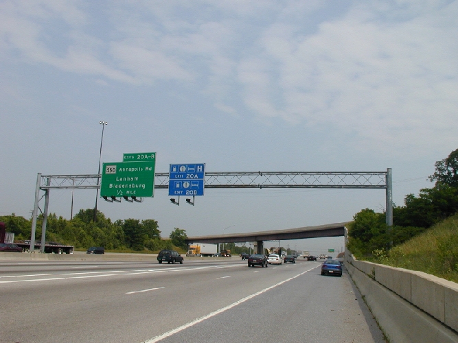
Sign Bridge Components – A sign bridge is constructed of the following components, which together define the structure:
- Sign bridge configuration – Five configurations are available in the program;
-
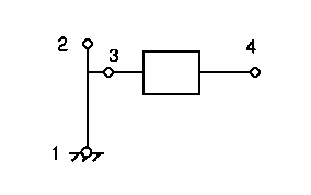
- Cantilever
-
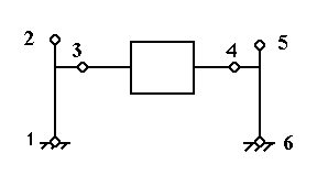
- Single Span
-
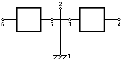
- Butterfly
-
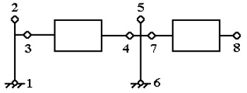
- Single Span with Cantilever
-
- Double Span
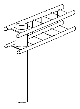
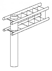
Tower types – Two types of towers are allowed, single post or double post. The tower post can be either prismatic or linearly tapered. The double posts can be trussed or non-trussed;
-
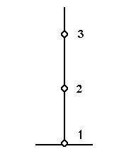
- Single Point
-
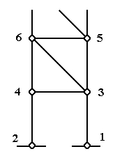
- Double Post
Beam types ?Four beam types are allowed;
-
- Monotube
-
- Plane Truss
-
- Trichord Truss
-
- Box Truss
Sign Bridge types – The four beam types and two tower types can be combined in six different ways;
Member types – The program includes four different member types;
Section types – In all, eight section types are recognized, four tubular shapes and four general shapes;
Sign types – Rectangular signs only;
Walkway types – Rectangular walkways mounted parallel to the bridge beams; -
-
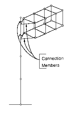
Vertical attachment member (VAM) types – Prismatic general shapes only.
The SIGN BRIDGE program contains several special features developed to make the program as easy as possible to use and to shorten the design/analysis cycle:
- Pull-Down Menu System – A Windows pull-down menu system is provided as a means of navigating about the program;
Data Entry and Editing – The user may move to any cell on a screen by using the mouse or enter key and move to any screen by using the pull-down menu system;
Automatic Joint and Member Renumbering – This eliminates the need to recalculate manually and enter the other joints and/or members after deleting or inserting;
Section Lookup – The user may call up this file onto the screen, review the data within it, and select a suitable section;
On-Screen Help – Pressing “Help” displays a window on the screen with information relevant to the current program level;
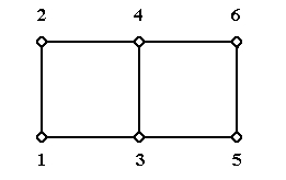
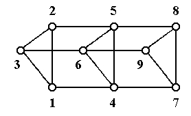
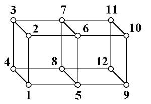
Automatic Mesh Generation – When used, the mesh generator can create all data required to define the joints and members of a sign bridge;
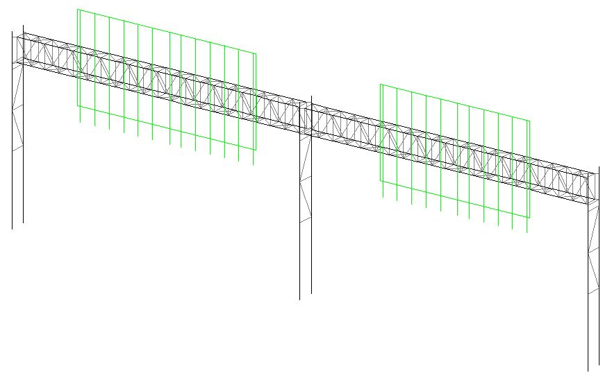
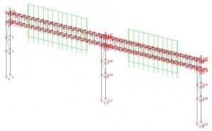
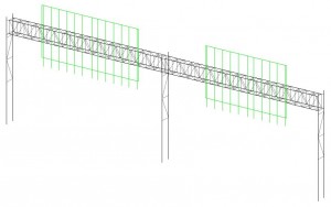
On-Screen Graphics – The graphic image consists of a wire frame representation of the structure and can be of the current structure being edited or a structure previously analyzed;
- Structural Analysis Capabilities – The SIGN BRIDGE program can analyze support structures for a wide variety of configurations, boundary conditions, member types, and loading conditions.
 Q&A
Q&A