Visual Bridge and Roadway Geometries
Abstract
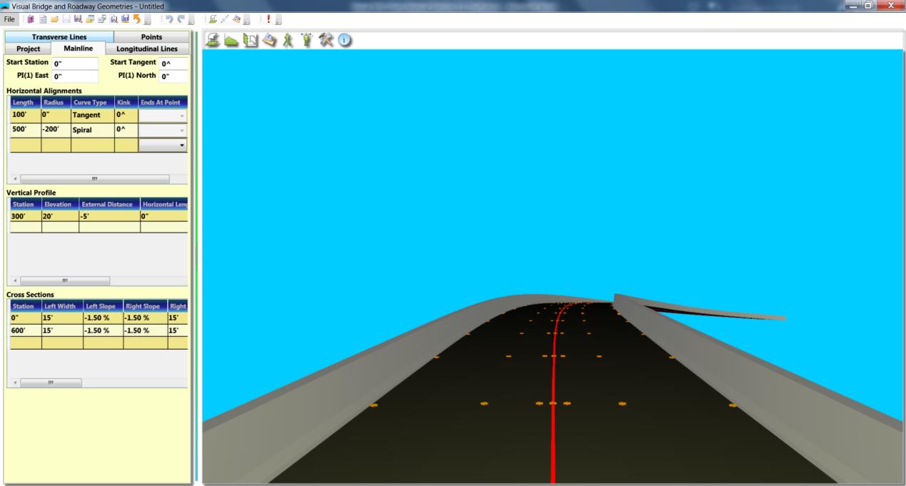
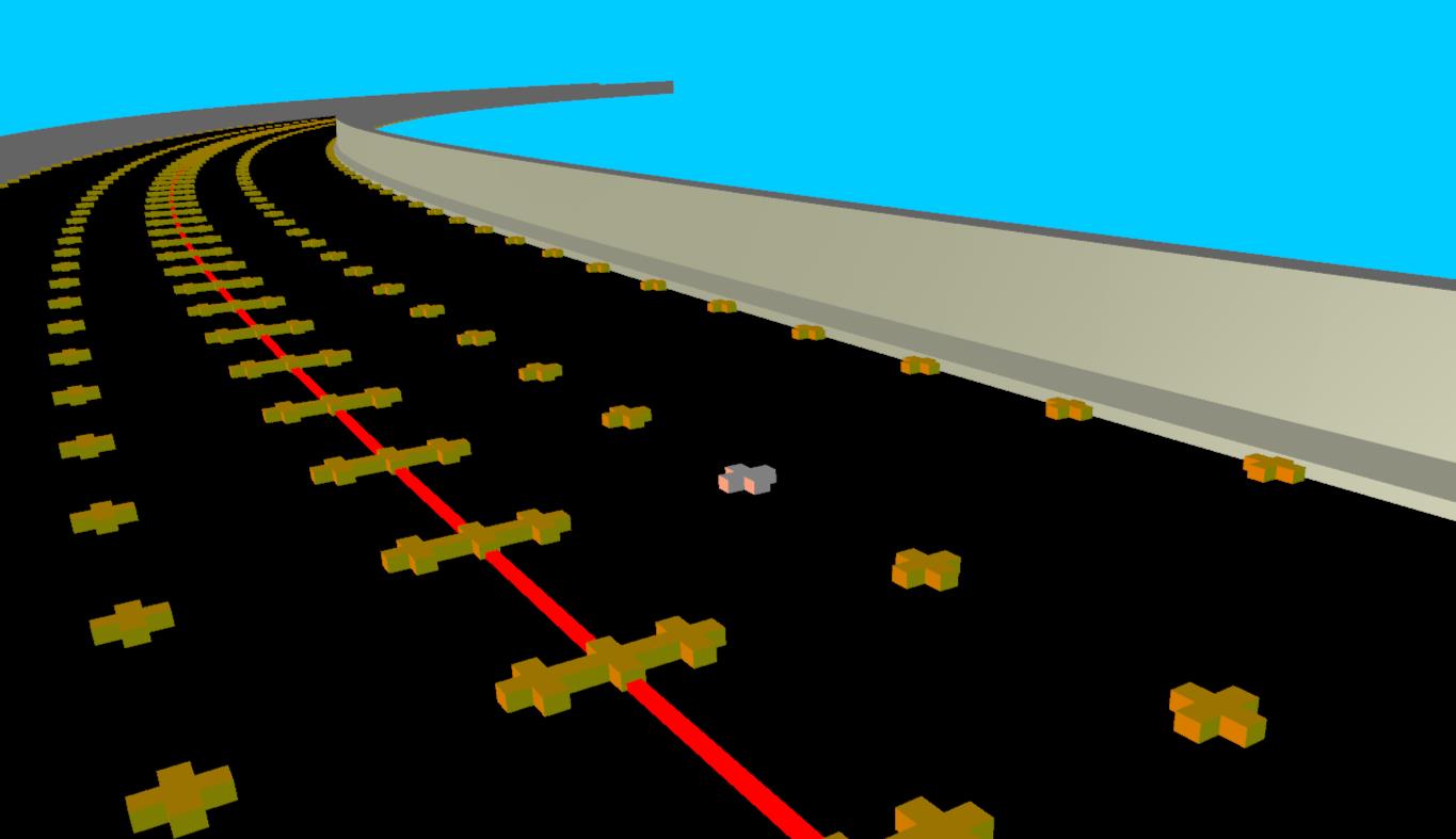
Roadway geometries including horizontal and vertical curves, super-elevations, superwidening and transverse curves can be modeled by “parametric” method. Bridge components such as supports, girders, diaphragms can then be defined on the basis of roadway geometries. Roadway cross sections at designated stations can be graphically shown on screen. Coordinates of bridge deck control points (longitude, latitude and elevation) can be exported as a data file so that it can be plotted in Microstation. As a supplemental feature to modeling bridge geometries, girders, diaphragms and supports information can be modeled seamlessly at the same time. To facilitate further structural analysis, such a bridge geometry model can be exported as a DESCUS data file so that it can be analyzed by using DESCUS programs. In addition to export functions, Visual BRG also provides import functions to allow users to build geometry models from AutoCAD Exchange File (DXF) or to reproduce bridge models from existing DESCUS program analysis data file.
Program Scope
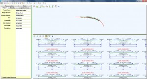
When Visual BRG starts, the main window as shown below will open. The main toolbar is on the top of the window. Left portion is the data forms area. Right portion is the graphics area. A default roadway and bridge model is preset initially.
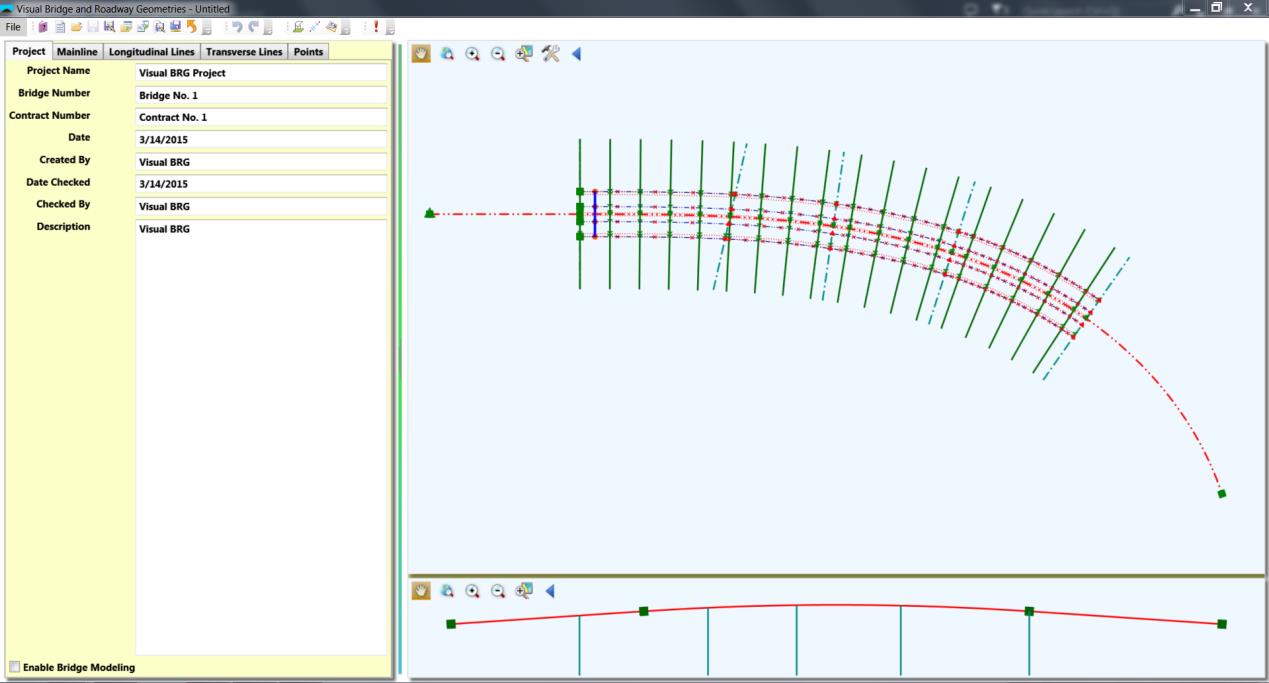
Transverse road curves of these cross sections are shown in 2D on the bottom of the window and roadway surface and railing can be rendered in 3D.