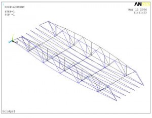
Top Chord Buckling Analysis
The buckling problem of the compressive top chord of a pony truss, or, as is called, half through truss, is a problem of members with elastic lateral restraints. Article 10.16.12.2 of the AASHTO Standard Specifications, 17th Edition, states:
10.16.12.2 The top chord shall be considered as a column with elastic lateral supports at the panel points. The critical buckling force of the column, so determined, shall exceed the maximum force from dead load, live load, and impact in any panel of the top chord by not less than 50%.*
with a footnote
* For a discussion of columns with elastic lateral supports refer to Timoshenko & Gere, “Theory of Elastic Stability,” McGraw-Hill Book Co., First Edition, p.112.
A similar statement can also be found in Article 6.14.2.9 – Half Through Trusses of the AASHTO LRFD Bridge Design Specifications, 2006 Interim Revision.
Timoshenko’s theoretical analysis was formulated on a spreadsheet file by Dr. C. C. Fu in his previous study. An alternate approach has been established and formulated by Dr. Fu by following the publication, “Guide to Stability Design Criteria for Metal Structures (SSRC, Structural Stability Research Council),” 5th Edition (1998), edited by T.V. Galambos.
 Furthermore, for verification, ANSYS software with the capability to solve 3-D finite element elastic buckling analysis is adopted to verify the overall buckling load based on the Timoshenko’s method.
Bridge Redundancy Analysis
Bridge redundancy, as defined in the NCHRP Report 406 (NCHRP, 1998), is the capability of a bridge to continue to carry loads after incurring damage or the failure of one or more of its members. This capability is due to redistribution of the applied loads in transverse and/or longitudinal directions. To analyze the redundancy of a bridge, the ideal solution would be to use a structural model and a finite element analysis package that consider the Aelastic@ and Ainelastic@ behaviors of the bridge members. This program should be capable of evaluating an intact bridge under the effect of heavy loads as well as considering different damage scenarios. There are also some safety related issues that should be addressed.
In view of the above, “the acceptability of the highway truss is highly dependent upon the analysis method which quantifies structural redundancy levels in the design and evaluation of the highway bridge system@ (Frangopole and Nakib, 1992). AIn this context, corrosion and accidental damage are stimulated.@ AThe redundancy measures used in evaluating the (design) offer useful information to quantify the effects of various damage states . . . and the availability of warning@ (Frangopole and Nakib, 1992) prior to collapse.
NCHRP Report 403 proposed a series of tables for system factors to be used in the design and evaluation equations for common-type bridges. The system factor tables developed in the NCHRP study are applicable to standard prestressed concrete and steel bridges. Bridges with configurations that are not covered by the tables have to be checked by performing a detailed incremental structural analysis. Steel truss bridge was mentioned specifically in this report to illustrate how the direct analysis can be applied in practice. This approach is allowed by PennDOT Design Manual Part IV, Section 3 – Loads and Load Factors. Commentary for Extreme Event IV states that:
“For this extreme event, a 3-D analysis is required. The objective of this analysis is survival of the bridge (i.e., the bridge may have large permanent deflections, but it has not collapsed).”
Thus, a three-dimensional (3-D) nonlinear model of the truss is recommended for the structural analysis. For this study, the safety analysis is proposed to be conducted as follows:
- Member Failure Check, Ultimate Capacity Check, and Functionality Check
- Damaged Condition Check
The intention is to prove that although this bridge geometry does not satisfy redundancy criteria, the conservatives of the member design ensure that enough system safety is still available.